UWB Knowledge Base

UWB Knowledge Base

Everything about Ultra-Wideband — technology fundamentals, bands and channels, ranging methods (TWR / TDoA / PDoA), ecosystem, market and applications. Curated from Chipsbank internal training material.

Overview

What is UWB

Updated 2026-04 · 6 min read

UWB (Ultra-Wideband) is an IEEE 802.15.4a/z standard technology optimised for secure microlocation. By measuring the time a radio signal takes to travel between devices, it can work out distance and position indoors or outdoors with unprecedented accuracy — down to a few centimetres.

Beyond centimetre-level accuracy, the standard also focuses on making UWB robust and immune to many forms of interference, ensuring high reliability. It was designed with low power consumption and low cost in mind, and it supports a very large number of connected devices.

UWB is already being used to solve problems across many industries and applications, including:

Keyless car entry

Digital car keys built on secure ranging — unlock as you approach, lock as you walk away.

Factory efficiency & safety

Locate people, tools and assets in real time; rapid headcount during emergencies.

Hospital asset management

Find essential supplies and medical equipment across a campus.

Smart home control

Point-and-control interaction that senses where a person is and what they intend.

Unlike other radio technologies, UWB is purpose-built for the precise, secure and real-time measurement of position, distance and direction, while still supporting two-way communication — it was never meant to replace Wi-Fi or Bluetooth for bulk data transfer, but to add a sense of perception.
Overview

Key Advantages

Updated 2026-04 · 5 min read

Time-of-Flight (ToF) ranging, not signal strength

One of UWB's key advantages is that it uses the time of flight of a signal to work out the distance between devices. This is far more accurate than the RSSI (received signal strength indicator) method typically used by Wi-Fi and Bluetooth.

High time resolution

UWB signals occupy far more bandwidth than common narrowband technologies. Because time and bandwidth are inversely related, UWB pulses are extremely short and their time resolution is very high, so ToF can be determined accurately. The high time resolution and short wavelength also make UWB signals far more resistant to multipath interference and fading.

Centimetre-level accuracy

Compared with radio technologies such as Wi-Fi or Bluetooth Low Energy (BLE), UWB is 100× more accurate, delivering precision in centimetres rather than metres. That matters when tracking small objects, or when you need to know which side of a wall something is on.

Ultra-low latency for real-time positioning

UWB has very low latency — on the order of microseconds to nanoseconds, versus tens or even hundreds of milliseconds for Wi-Fi and Bluetooth. UWB is 50× faster than GPS and can update up to 1,000 times per second, three thousand times faster than a standard BLE beacon. That makes it ideal for automation systems and applications involving fast-moving objects such as drones.

Wide bandwidth, high-speed communication

The wide bandwidth also makes UWB suitable for high-speed communication. And because UWB uses the ToF information and distance-bounding techniques defined in IEEE 802.15.4a/z, it offers stronger security than other wireless technologies that sense distance and position.

100×Positioning accuracy advantage over Wi-Fi / BLE
1,000/sMaximum position update rate
50×Speed advantage over GPS
CentimetresTypical ranging accuracy

Overview

The Future of Microlocation

Updated 2026-04 · 4 min read

UWB's greatest potential lies in an entirely new generation of microlocation systems. Just as Wi-Fi and GPS paved the way for applications that were previously hard to imagine, UWB will enable experiences and features built on highly accurate position and distance sensing.

Today, people expect to locate almost anything in real time, whatever its size:

  • Being guided straight to your car keys when they go missing at home;
  • Getting shelf-level navigation to your favourite coffee brand in a grocery store;
  • Finding a specific tool in a storage bin on a factory floor;
  • As a site manager during an emergency, confirming that everyone has left the building.

In all of these scenarios microlocation helps — it does not just tell you "where" something is, it guides you to where it actually is.

Technology

Technical Features

Updated 2026-04 · 5 min read

UWB (Ultra-Wideband) is a wireless communication technology (based on IEEE 802.15.4a/z) characterised by transmitting narrow pulses across a wide range of frequencies, typically with an extremely short pulse width (nanoseconds). UWB uses these narrow pulses to carry data, and its transmission and modulation differ greatly from conventional carrier-based technologies such as Wi-Fi and Bluetooth.

Wide Spectrum

Uses a broad swath of spectrum for data transmission (from hundreds of MHz up to GHz-scale bands), improving spectrum efficiency.

Narrow Pulses

Data is carried by extremely short pulses spread across frequency, giving strong interference resistance and good penetration.

High Speed

Achieves high data rates, typically at low power consumption.

High Resolution

High time and spatial resolution, suitable for a variety of ranging algorithms.

Power spectral density (PSD) — UWB spreads a very wide bandwidth at extremely low power over 3.1–10.6 GHzGPS 1.6GBLE / Zigbee 2.4GWi-Fi 2.4/5GUWB 3.1–10.6 GHz≥500 MHz bandwidth

Technology

Bands & Channels

Updated 2026-04 · 5 min read

The UWB frequency range defined by the FCC is 3.1 GHz to 10.6 GHz. Within this range, IEEE 802.15.4 defines multiple channels (Channel 0–15); the channels opened vary slightly by country and region.

UWB channel list

ChannelCarrier frequency (MHz)Bandwidth (MHz)Country / Region
0499.2499.2Proprietary
13494.4499.2US, EU
23993.6499.2US, EU, Japan, South Korea
34492.8499.2US, EU, Japan, South Korea
43993.61331.2US, EU
56489.6499.2US, EU
66988.8499.2US, EU
76489.61081.6US
87488.0499.2US, EU, South Korea, China
97987.2499.2US, EU, Japan, South Korea, China
108486.4499.2US, EU, Japan, South Korea, China
117987.21331.2US, Japan, South Korea, China
128985.6499.2US, Japan, South Korea
139484.8499.2US, Japan, South Korea
149984.0499.2US, Japan, South Korea
159484.81354.97US, Japan, South Korea

Chipsbank's CBU5000 series UWB SoC operates in the 6–9 GHz second band group and supports Channel 5 / 6 / 8 / 9 / 10.

Technology

Capabilities

Updated 2026-04 · 4 min read

As an exceptional secure ranging technology, UWB excels across five dimensions:

Accuracy

±10 cm error, hundreds of times more accurate than other radio technologies such as Wi-Fi or BLE.

Performance

UWB pulses arriving over multiple paths are extremely short and do not interfere with each other; the receiver can still distinguish the pulses it receives, giving strong performance in multipath environments.

Real-time

No latency: microseconds to nanoseconds, versus tens or hundreds of milliseconds for Wi-Fi or BLE. Refresh rate 200–1,000 times per second.

Security

Uses the distance-bounding communication defined in IEEE 802.15.4a/z combined with ToF information. Signal-strength-based ranging is easily spoofed by a relay, whereas with ToF ranging a relay increases the arrival time and makes the measured distance longer, defeating the attack.

Range

Around a hundred metres in line of sight.

Technology

UWB vs Wi-Fi / BLE

Updated 2026-04 · 3 min read

The table below compares the parameters of UWB, Wi-Fi and BLE positioning (for reference only):

TechnologyUWBBLEWi-Fi
Frequency range3.1–10.6 GHz2.4 GHz2.4 / 5.8 GHz
Data rateUp to hundreds of MbpsUp to 2 MbpsUp to Gbps
Positioning latency<1 ms3–5 s3–5 s
RangeBest 0–50 m, up to 200 mBest 0–25 m, up to 100 mBest 0–50 m, up to 100 m
Positioning accuracy<10 cm, angle <3°RSSI: 5–10 m; AoA: 0.5–1 m<10 m
SecurityHigherHighHigh
PenetrationStrongWeakStrong
Anti-interferenceStrongWeakStrong
Power consumptionLowLowerHigh

As you can see: BLE positioning latency runs to seconds and its accuracy is metre-level; Wi-Fi is fast but power-hungry, and its positioning accuracy is also metre-level. Only UWB delivers millisecond latency + centimetre accuracy + low power at the same time.

Ranging & Positioning

How UWB Ranging Works

Updated 2026-04 · 6 min read

Narrow-pulse modulation: BPSK and BPM

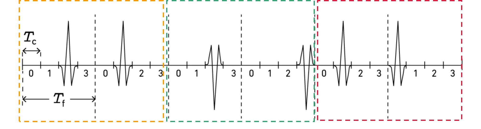
Unlike other radio technologies, UWB does not use amplitude or frequency modulation to encode the information its signal carries. Instead, UWB uses very short sequences of narrow pulses (just 2 nanoseconds), encoding data with binary phase shift keying (BPSK) and/or burst position modulation (BPM). These narrow pulses also have clean edges, so the time of arrival and the distance can be determined precisely even when multipath effects from reflections are present.

In the BPSK example below, two consecutive impulse radio (IR) signals represent one symbol. An IR signal can occupy one of the chip intervals (Tc) within a frame (Tf). A time-hopping (TH) code determines the precise position of the signal within its dedicated time frame, reducing the chance of interference between UWB systems. In the example, the TH codes of the symbols are {2, 1}, {2, 3} and {1, 0}, so the first and second signals are shifted by two and one chip interval respectively, and so on. Here the information corresponds to the polarity of the signal, so the IR stream represents the binary data "101".

BPSK impulse radio signal example: frame time Tf, chip interval Tc and time-hopping TH code
BPSK pulse modulation: within a frame Tf, IR signals occupy different chip positions according to the time-hopping (TH) code; polarity carries the binary information.

ToF: time × speed of light = distance

Combined with the use of ToF information, this lets UWB compute an accurate distance estimate even indoors, where multipath reflections are common. Using timestamped signals, UWB calculates the time the signal takes to travel between devices, then multiplies that time by the speed of the signal (the speed of light) to obtain the distance.

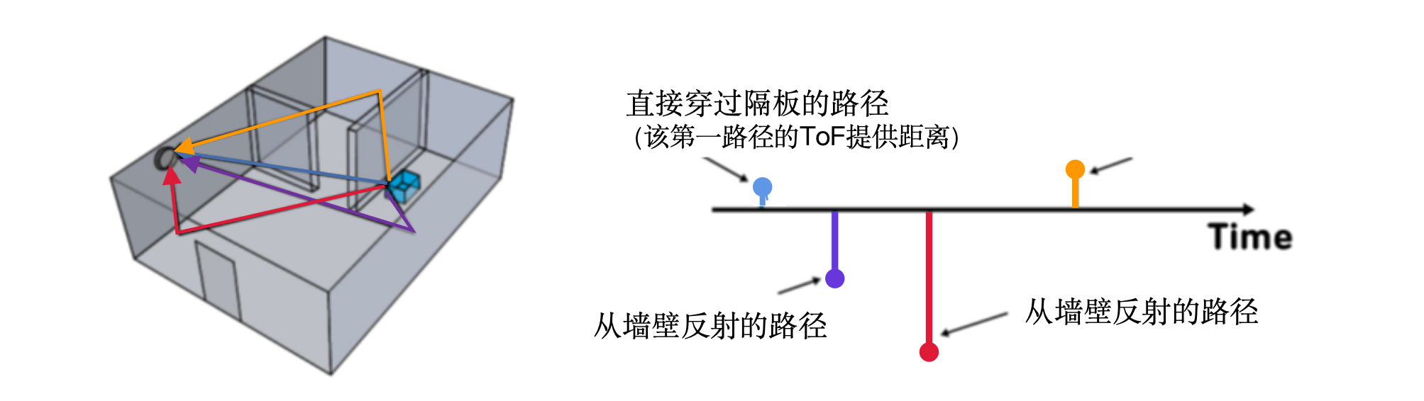
The figure below shows the advantage of using ToF to compute distance indoors. In the figure, the UWB signal transmitted by the blue device reaches the grey device on the wall by several different paths. One path goes directly through the intervening wall to the grey device; the other paths are longer because they involve reflections. Because the direct path is the shortest, it arrives at the grey device first and is used to compute ToF. The other signals can be ignored. Think of it as a race: many runners reach the finish line, but only the first one wins.

ToF ranging in an indoor multipath environment: the direct path arrives first, reflected paths follow
First-arriving path in a multipath environment: the direct signal arrives first and is used to compute ToF; later reflected paths do not affect the result.

This method is unaffected by signal strength, so if the direct signal is attenuated after passing through an intervening wall, the result is not affected.

Ranging & Positioning

SS-TWR

Updated 2026-04 · 5 min read

To understand distance and position measurement with UWB, it is important to know the terms "anchor" and "tag". An anchor is typically a fixed UWB device at a known position. A tag usually means a mobile UWB device. Anchors and tags exchange information to establish the distance between them. By communicating with multiple anchors, the precise position of a tag can be determined. Some devices can act as anchor, tag, or both — for example, when two phones use UWB to work out the distance between them, they may alternate between the tag and anchor roles during the process.

Two-Way Ranging (TWR) determines the time (ToF) a UWB radio signal takes to travel back and forth between tag and anchor, then multiplies that time by the speed of light to compute distance. Keyless car entry systems are a classic example of using TWR for secure and accurate distance determination.

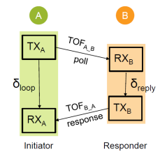
Single Sided – Two Way Ranging (SS-TWR)

The transmitter (A) sends a Poll signal to receiver B.

δreply is the time from B receiving the signal to sending its response — effectively the processing time (delay) inside the receiver. Since ToFA→B = ToFB→A, the transmitter knows the total time from transmission to reception.

Therefore: δloop = 2 × ToFA→B + δreply

So we can compute ToFA→B = (δloop − δreply) / 2, and hence the distance: distance = ToF × speed of light.

SS-TWR two-way communication flow: TX/RX exchange between Initiator A and Responder B
SS-TWR flow: A acts as Initiator and sends a poll; B, as Responder, receives it and replies with a response. A subtracts B's processing delay from the loop time to obtain the two-way time of flight.

Ranging & Positioning

DS-TWR

Updated 2026-04 · 4 min read

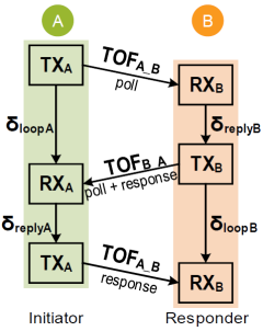
DS-TWR: Double Sided Two-Way Ranging

SS-TWR is simple, but the clock reference difference between transmitter and receiver introduces ToF error. Chipsbank has done extensive development work to address this shortcoming of SS-TWR by compensating for the clock error: clock frequency error is generally at the ppm level and can be compensated down to ppb. When signal strength is poor, ranging error exceeds 2 m without compensation; with compensation we can reduce the error to less than 2 cm.

If Chipsbank's clock compensation scheme is not used, Double Sided Two-Way Ranging (DS-TWR) can solve this problem, as shown below.

Each device can compute its own ToF, and then improve measurement accuracy by compensating for the clock differences between the two devices.

This method consumes more power because it involves the transmission of three frames.

DS-TWR three-frame exchange: poll / response / final between Initiator A and Responder B
DS-TWR uses three frames (poll, response, final) so that A and B each compute the loop and reply times, cancelling out clock error.
DS-TWR ToF calculation formula
DS-TWR combines the δloop and δreply values from both A and B to obtain a more accurate one-way ToF.

Ranging & Positioning

TDoA

Updated 2026-04 · 5 min read

TDoA: Time Difference of Arrival

Time Difference of Arrival (TDoA) is a highly scalable way to determine the position of tags within a venue. Because a tag only needs to transmit once during the whole process, it consumes very little power and therefore has a very long battery life.

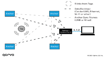
Multiple anchors are deployed at fixed, known positions and tightly time-synchronised. When a mobile device sends a "beacon" or "blink" signal, every anchor that receives it timestamps the arrival against a common synchronised time base. The timestamps from the anchors are then forwarded to a central location engine, which runs multilateration algorithms to determine the device's position from the differences in arrival time at each anchor. The result is a 2D or 3D position of the mobile device, as shown below. This method is commonly used in RTLS (Real Time Location Systems).

TDoA positioning architecture: multiple anchors receive a tag blink, timestamp it and forward the data to a gateway plus location engine
TDoA architecture: multiple anchors timestamp tag blinks against a synchronised time base and send them to a central location engine that computes X, Y, Z.

Reverse TDoA: a GPS-like mode

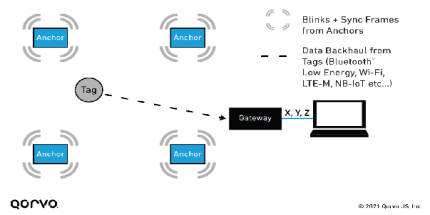
Reverse Time Difference of Arrival (Reverse TDoA). A reverse TDoA system similar to GPS can also be implemented. The anchors transmit synchronised blink signals (with fixed, known offsets to avoid collisions), and the mobile devices use TDoA and multilateration to compute their own positions, as shown below.

Reverse TDoA architecture: anchors send blinks and sync frames; the tag receives them, computes its own position and sends data back via BLE, Wi-Fi, LTE-M, etc.
Reverse TDoA: anchors transmit synchronised signals and the device solves its own position, with no need to send raw timestamps back to a central engine — inherently better for privacy-sensitive scenarios.

Ranging & Positioning

PDoA

Updated 2026-04 · 4 min read

PDoA: Phase Difference of Arrival

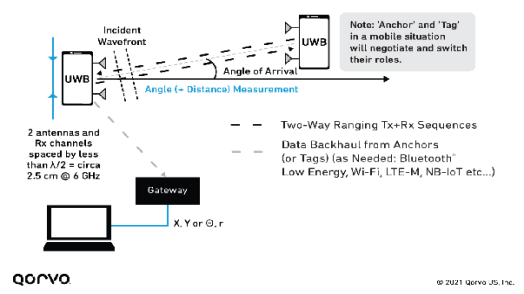
Phase Difference of Arrival (PDoA) lets two devices work out their relative position without any other infrastructure, using a combination of distance and direction information. This matters for peer-to-peer applications, or for reducing the amount of infrastructure that has to be deployed.

For PDoA, one of the devices must carry at least two antennas. When that device receives a signal from the other device, it measures the phase difference of the arriving signal at each antenna and converts the measured phase difference into a distance difference: P = λ × Δφ / (2π). With the distance obtained from time of flight, the rest is high-school mathematics — a few equations give the direction of the incoming signal.

PDoA principle: an anchor/tag uses the phase difference between two antennas to measure the direction and distance of the incoming wave
PDoA principle: the phase difference of the arriving signal is measured with at least two antennas, converted into a distance difference and combined with the ToF distance to solve the direction of arrival and the relative position.

The receiving device now knows the direction and distance of the transmitting device — the physical basis for "spatial awareness" interactions such as connecting to whichever device a phone is pointed at. Chipsbank's CBU5000 1T3R architecture can further deliver 3D AoA (three-dimensional angle of arrival).

Ecosystem & Market

Vendor Landscape

Updated 2026-08 · 6 min read

The market is at an inflection point: UWB is moving from flagship experimentation to large-scale deployment, and mainstream vendors are making UWB standard on phones, wearables, automotive digital keys and trackers. Below are the latest developments from the major vendors in 2025–2026 (from public reporting and vendor announcements).

Apple

In January 2026 Apple released the second-generation AirTag with the same second-generation ultra-wideband (U2) chip as iPhone 17. Precision Finding range is about 50% greater than the first generation, and for the first time precise location is supported directly on Apple Watch (S9 and later, Ultra 2 and later, watchOS 26.2.1+). iPhone 15 and later (except iPhone 16e) benefit from longer-range finding; iOS 26 adds Share Item Location, already working with 50+ airlines to reduce lost luggage.

Samsung

Galaxy SmartTag 2 already uses UWB plus Bluetooth 5.3, delivering centimetre-level directional guidance with SmartThings Find and Compass View. Multiple reports indicate Samsung plans to launch Galaxy SmartTag 3 alongside the Galaxy S26 FE in September–October 2026, with major upgrades to UWB precision positioning plus Bluetooth 5.4, IP68, a louder speaker and a programmable smart button, clearly targeting AirTag.

Xiaomi

Xiaomi 17 Pro / 17 Pro Max use Qualcomm's FastConnect 7900 (integrating Wi-Fi 7, Bluetooth and UWB), making UWB a flagship selling point; the Xiaomi 17 Ultra has built-in UWB that works as a digital key for the Xiaomi YU7 (unlock on approach, lock on leaving, open the front and rear boots). From "One-touch Connect" on the Mi 11 Ultra through the 15S Pro to the 17 series, UWB has become a flagship standard in Xiaomi's ecosystem.

Huawei

Huawei is a pioneer in UWB car keys: the Mate XT tri-fold was the world's first to support the UWB key for the Fang Cheng Bao Bao 8 (unlock on approach, lock on leaving), with Huawei Watch unlocking also supported; the Denza N9 and N8L have also been integrated with Huawei UWB. Notably, as its NearLink SLP protocol rises, Huawei's technical roadmap is gradually shifting towards NearLink, and some models are beginning to adopt the new standard.

Qualcomm

FastConnect 7900 has landed on platforms such as Snapdragon 8 Gen 5 — a single chip integrating Wi-Fi 7, Bluetooth and UWB, with AI-based power and performance optimisation, popularising UWB digital car keys and indoor navigation across more Android flagships. At MWC 2026 (March 2026), Qualcomm further announced FastConnect 8800 as its successor: again integrating UWB (802.15.4ab), Wi-Fi 8, Bluetooth 7 and Thread 1.5 on one chip, and adopting a 4×4 RF architecture for the first time (the 7900 was 2×2), doubling peak throughput to 11.6 Gbps and roughly tripling coverage, plus Proximity AI that combines UWB and Wi-Fi ranging. The chip is expected to reach mass production by the end of 2026 with the next-generation Snapdragon flagship platform, extending UWB car keys and indoor navigation to a broader Android camp.

Google

The Android UWB Jetpack library has supported the Pixel Pro series, Pixel Fold, Pixel Tablet, Motorola Edge 50 Ultra and Samsung flagships since January 2025; the entire Pixel 10 Pro line carries UWB, working with Find Hub precise finding and Google Wallet UWB digital car keys (BMW, Hyundai, Kia, Mercedes-Benz and others). However, some older Pixels (6/7 Pro) have UWB hardware but precise finding was never enabled.

Chip vendors and standards progress

NXP

The Trimension family continues to evolve: the NCJ29D6 passed FiRa Core 3.0 certification in December 2025 and, as an automotive-grade UWB IC, was first to complete CCC Digital Key interoperability certification with BMW — one of the main chips for digital car keys.

Qorvo

In March 2025 it launched the third-generation UWB SoC QM35825 (all-in-one, with 4 RF ports plus Cortex-M33, ranging accuracy ±5 cm, AoA ±2°), alongside the automotive-grade QPF5100Q; in May 2026 it released the QPK3000 module, embedding UWB RTLS directly into enterprise Wi-Fi access points and greatly reducing deployment cost.

FiRa / CCC standards

The FiRa Consortium released the Core 3.0 specification in 2025, and Core 4.0 in 2026 added UL-TDoA and Aliro (smart home access) support; CCC Digital Key 3.0 defines UWB as the precise ranging layer, and in 2025 certification was extended to BLE+UWB, with 115 products certified over the year, covering BMW, Audi, NIO and XPeng.

Ecosystem & Market

Market & Growth

Updated 2026-04 · 4 min read

UWB is spreading across more markets. ABI Research forecasts that global shipments of UWB devices will grow at a compound annual growth rate of 14% over the next five years, from 435 million units in 2023 to nearly 1.3 billion in 2028. Chip suppliers, large and small, recognise the opportunity UWB represents.

435M → 1.3B units2023 → 2028 global UWB device shipments (ABI Research)
14% / year2023–2028 compound annual growth rate (CAGR)
21%Share of smartphone shipments that already included UWB last year
Nearly 50%Share of smartphones that will include UWB by 2028

Last year, 21% of smartphone shipments included UWB technology, including phones from Apple, Samsung, Google and Xiaomi; according to ABI Research, by 2028 almost half of all smartphones will include UWB.

Application market distribution

UWB applications span multiple markets: IoT, automotive, wearables, smart home, consumer electronics, home entertainment and connected home devices, portable consumer electronics, networking, PCs and their accessories, smartphones and feature phones, and more. As a secure short-range wireless tool with centimetre-level accuracy, every new product launch and every new market entrant continues to validate the potential and the prospects of this technology.

Applications

Use Case Overview

Updated 2026-04 · 4 min read

UWB will quickly become part of our daily life and work. The range of application scenarios includes:

Smart retail

Tag markets, touch-free mobile payment, unmanned stores, footfall analytics, shopping behaviour analysis, targeted marketing.

Smart city / transport

Indoor navigation, vehicle digital keys, rider identification, ticket validation, fare payment, parking access control.

Smart home

Residential access control, augmented reality games, gesture-based control, virtual reality games, finding nearby people or objects, device activation.

Smart manufacturing

Controlled access, physical access control, indoor navigation, emergency mustering of staff, asset tracking, equipment finding.

Standards & Frontier

IEEE 802.15.4ab

Updated 2026-08 · 7 min read

The UWB technology family keeps evolving on top of the IEEE 802.15.4 standard: 4a introduced the HRP-UWB PHY for ranging and positioning; 4z strengthened secure ranging on that basis; and 802.15.4ab is best described by the phrase "capability expansion". If 4z was about whether the measurement is secure, 4ab asks: now that UWB is in phones, cars, IoT, smart homes and industry, what further capabilities are needed to support the next generation of short-range wireless applications?

What 4ab enhances

802.15.4ab enhances the UWB PHY, MAC and related ranging techniques while remaining backward compatible with ERDEV (Enhanced Ranging Capable Devices, introduced in 4z). The scope of the enhancements is very broad:

  • Extensions to coding, preamble and modulation schemes;
  • New operating frequencies and interference mitigation (coexistence);
  • High-integrity ranging and low-power mechanisms;
  • Narrowband assist;
  • UWB sensing (radar-style sensing);
  • Low-power low-latency streaming and high-data-rate streaming.

Four device capability classes for HRP-UWB

Building on the HRP-ERDEV of 4z, 4ab further defines and strengthens HRP-EMDEV, and introduces HRP-SDEV, HRP-ARDEV and HRP-LLDDEV, pushing UWB from "ranging" towards a "multi-capability platform":

HRP-EMDEV (base enhanced layer)

The base enhanced mode of 4ab: mandatory support of the K=7 convolutional code for PHR and Payload, and support for rates such as 1.95 / 62.4 / 124.8 Mbps. Stronger coding, richer modulation and more flexible data rates lay the foundation for later low-latency data, enhanced ranging and sensing.

HRP-SDEV (standardised sensing)

Standardises UWB's move from ranging and positioning to radar sensing. SENS configuration 0 is mandatory, 1 and 2 optional, and SENS reuses the same preamble code as SYNC/SFD. Its sensing pulse shape requirements are stricter than ERDEV — energy both before and after the pulse must stay below 4% (ERDEV constrains only pre-pulse energy) — so that echoes can be interpreted cleanly.

HRP-ARDEV (enhanced ranging)

Further improves the integrity and accuracy of ranging on top of ERDEV, for scenarios with higher requirements on secure ranging such as digital car keys.

HRP-LLDDEV (low-latency / low-power data)

Targets low-power low-latency streaming and high-data-rate streaming — scenarios that need to "transmit data while ranging", letting UWB carry communication tasks as well.

Standards & Frontier

FiRa Consortium

Updated 2026-04 · 4 min read

The FiRa Consortium is a member-driven organisation dedicated to transforming the way we interact with our environment by exploiting the secure, precise positioning capabilities of ultra-wideband (UWB) technology, giving people and devices precise location awareness. FiRa ensures interoperability between different chips, devices and solutions by advancing technical specifications and certification, advocating effective regulation, and defining a broad set of UWB use cases.

Core Specification 2.0

FiRa has successfully released version 2.0 of its core technical and test specifications, supporting three new use cases: indoor navigation, finding a person or an object, and point-and-touch control of smart home devices.

Certification Program 2.0

FiRa announced an expanded Certification Program 2.0, giving FiRa members the ability to develop UWB products that support the new use cases, and driving adoption of UWB technology.

Corporate members

Globally advanced electronics and semiconductor manufacturers such as Apple, Cisco, Google and Huawei, as well as leading laboratories and academic institutions.

Strategic alliances

FiRa has established a strategic alliance with the CCC (Car Connectivity Consortium) to ensure seamless interoperability and scalability of the cutting-edge UWB technology developed for the CCC Digital Key.

UWB Radar

Radar Sensing

Updated 2026-08 · 6 min read

Conventional UWB applications usually involve two devices communicating, computing distance from the signal's time of flight and optionally determining direction with multiple antennas. UWB radar works differently: the device actively transmits ultra-wideband pulses and simultaneously receives the reflections from people, vehicles, furniture and walls. By analysing how the continuous reflected signal changes, it works out what is happening in the space.

Four characteristics of UWB radar

Non-imaging sensing, privacy-friendly

It does not capture faces, images or sound directly — it only analyses changes in the reflected radio signal (whether someone is there, whether they are moving, which zone they are in). Ideal for privacy-sensitive spaces such as bedrooms, elderly care, hotel rooms, meeting rooms and TV interaction.

From "someone is here" to "where they are"

Unlike conventional PIR, which only detects obvious thermal motion, UWB radar combines distance, direction and zone information to tell whether a person is approaching, has entered a defined area, is still there, is moving closer / away / stationary, and which zone has changed — moving towards finer-grained spatial understanding.

Sensing micro-movements

A person who is standing still still has chest and abdominal micro-motion from breathing. With time-series analysis, filtering and tracking algorithms, breathing-related trends can be extracted — suitable for static presence confirmation, sleep assistance, elderly and infant care, and contactless interaction.

Converged with ranging, pointing and interaction

The same UWB platform can be combined as needed to deliver precise ranging, pointing determination, presence sensing, zone detection, trajectory tracking, micro-motion and breathing trend sensing, secure interaction and digital keys — rather than a set of independent modules.

Industry progress: from positioning to converged sensing and interaction

FiRa released the Core 4.0 specification and certification program in 2025, continuing to advance interoperability and ecosystem adoption among UWB devices. The industry is also exploring UWB for presence detection, child presence detection (CPD) in vehicles, micro-motion sensing such as breathing, and contactless interaction in smart homes and consumer electronics. UWB is evolving from a technology that "finds devices" into a capability that lets devices understand a user's position, behaviour and spatial state.

Chipsbank's UWB radar progress

Around the deployment of UWB radar in consumer electronics and smart spaces, Chipsbank has completed multiple solution validations and continues to advance the optimisation of algorithms, antennas, mechanical design and overall user experience:

  • Outdoor two-wheeler sentinel radar: senses whether someone is approaching the vehicle, whether a target has entered a defined area and how it is moving, assisting with parking, charging, parked-vehicle watch and anti-theft alerts; it can trigger alarms, lights and cameras without depending on a camera.
  • TV pointing and radar working simultaneously: lets a TV maintain spatial awareness while supporting remote-control pointing interaction, better understanding the user's intent, so that positioning, pointing and radar sensing cooperate rather than working independently.

Appendix

Glossary

Updated 2026-04 · 3 min read

Explanations of some terms commonly seen in the UWB field:

AbbreviationFull termExplanation
IEEEInstitute of Electrical and Electronics EngineersThe world's largest professional association for electrical, electronic and computing fields and related science and technology. Common standards such as Wi-Fi and Ethernet are defined by it.
ToFTime of FlightThe time a signal takes to travel from one point to another.
LoSLine of SightIn a physical radio channel configuration, a direct line of sight exists between transmitter and receiver.
NLoSNon Line of SightIn a physical radio channel configuration, there is no direct line of sight between transmitter and receiver — for example, a wall in between.
RTLSReal Time Location SystemA system designed to provide real-time location information about various items.
TWRTwo Way RangingA ToF-based distance measurement method, computed from two-way communication between transmitter and receiver.
TDoATime Difference of ArrivalA method of deriving transmitter position information. It records the arrival times of transmissions at two physically different locations (whose clocks are synchronised); the difference in arrival times provides information about the transmitter's position. Multiple TDoA measurements at different locations can uniquely determine the transmitter's position.
PDoAPhase Difference of ArrivalA method of determining the propagation direction of a radio wave arriving at an antenna array, from the phase difference of the signal received at each antenna array element.